Web Energy Logger
- - What is the WEL?
- - How does it work?
- - Purchase Online
- - User Map / Info.
- - OurCoolHouse
Tech Support
WEL Logging (Users)
WEL Display (Users)
How does the Web Energy Logger (WEL) work?
 We know that the Web Energy Logger is an Internet Appliance designed to monitor a 1-wire sensor network, and post temperature and power data to a web site, but "how does it really work?"
That's the question I'll try to answer here.
We know that the Web Energy Logger is an Internet Appliance designed to monitor a 1-wire sensor network, and post temperature and power data to a web site, but "how does it really work?"
That's the question I'll try to answer here.
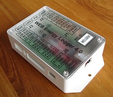
The WEL 4.0 is a small electronics assembly that uses an Ethernet-ready computer core from ZWorld, a 1-wire interface module from iButtonLink, and some pretty cool software (by me) to pull together all the functions needed for a roll-your-own temperature/energy logging system. In a nutshell, the WEL periodically reads all of its sensor inputs, scales and filters them, and then posts the values to an external Web Site. (Here's the User Guide.)
The primary destination for data is an off-site HTTP Web Server. The WEL can be configured to post to ANY server, however, I've set up a dedicated server (called WELServer.com) capable of displaying and logging the posted data. This Web Server is reached using the WEL's onboard Ethernet interface. The connection to WELServer.com is usually achieved by plugging the WEL into a home's LAN so it can access the home's broadband internet connection (DSL, cable, etc.)
Note: The WEL does NOT have any historic data storage on-board. So the WEL MUST be able to reach the outside Internet to post it's data to WELServer.com once a minute.
A secondary destination for data is a standard TTL serial port. This can be used to send sensor data to a local data logger (eg: Logomatic).
The WEL also has a tiny on-board Web Server of it's own, and this is used to configure the various operating parameters. Any local computer with a web browser can be connected to the WEL's LAN and be used to change system parameters. This local Web Server can also display the sensor data as a simple XML file for any other local internet devices to access.
Here is a block diagram for the WEL. Each of the blocks is described below. Additional details can be obtained from the WEL User manual located on the Support Files page of this site.
1-Wire Interface
The WEL uses an advanced 1-Wire interface module to communicate with addressable sensors on a shared external bus. The WEL supports both the two conductor "Parasitic" bus mode, and the three conductor "Powered" bus mode. Screw terminals are provided for connection to the 1-Wire bus. In the simplest installation, a single twisted pair of wires is routed throughout the area to be monitored, and each sensor is "clipped" onto the pair using in-line T-splices. Currently only the DS18S20 and DS18B20 sensors are supported. More will be added in the future. The maximum number of sensors that can be installed depends on the final wiring configuration (bus vs star vs random) but with suitable wiring, up to 100 sensors should be quite possible.
At power-on or reset, the system "searches" for all available 1-wire devices.
These are marked as "Found" and are available for subsequent polling.
A LED status indicator flashes each time the 1-Wire bus is scanned. Scans
occur every 6 seconds.
Watt-Meter Interface
Part of any energy study includes measuring the electrical power consumed by an installation. The WEL can monitor up to 6 external pulse-output watt meters. A typical system might measure a home's Net energy usage, plus the output of a PV array. The WEL was designed to work with Pulse output Wattmeters from Continental Control Systems. These meters are economical, accurate, and can be purchased for several different types of electrical load. Pairs of wires runs from each meter to the WEL, and connects via screw terminals. The WEL measures average power load each minute, and can calculated daily and monthly energy consumption.
A status LED indicates when power is being measured by any of the channels. The more power being used, the faster the LED flashes.
Local Run Monitor
Eight contact-closure sense-inputs are available on the WEL. These are used to sense external switching of equipment. A common "return" is provided for the eight inputs. The WEL can sense when any of the inputs have been shorted to the "Return signal. Dry contact relays or optically isolated outputs can be used as inputs. No active voltage (AC or DC) may be connected to these inputs.
0-10V Analog inputs
Two 0-10V inputs are provided for reading gauges. These
might be pressure or flow gauges. Expect about 1-2% accuracy on these.
Note: Earlier WEL models had 4-20mA inputs. These can still be special ordered with a 1 week lead time, at no additional expense.
Sensor Polling
Polling is a pure software function. 1-Wire inputs and Run inputs are polled every six seconds (0.1 Minutes). Power meter inputs are accumulated every 60 seconds. Raw input values are stored for further processing. The current sensor values are available for instant viewing via the local web server. If a "found" sensor does not respond during polling, or fails to return a valid value, it's status is set to "invalid" which prevents it's data from being posted.
Scaling and Filtering
Raw sensor values are "converted" to real world values by the scaling function. Each sensor can have a different scale if need be. The initial scale and offset for temperature sensors defaults to the Fahrenheit scale, but this can be changed by the user. The initial power meter scale defaults to that required by 100A current transformers. After scaling, values are time-filtered to produce a more smoothed result.
User Name Assignment
Each sensor is assigned a unique address by the system (or the 1-wire protocol), but these can be long and cumbersome. So, to simplify logging, each sensor is also assigned a logical "Name" by the user. These are typically short text strings that indicate function and location... eg: Z1,Z2,Z3 for zone temperature sensors or S1,S2,S3,S4 for slab loops. Users are encouraged to make names as meaning full as possible, while still keeping them short. eg: Z1S, Z1R & Z1A for Zone 1: Supply, Return and Air temperature.
Names are assigned interactively using the local web server User Interface. Names should be assigned as sensors are physically added to the 1-Wire network, because once many sensors are added, it can be difficult to tell them apart. Once names are assigned to sensors, these names are used when data is posted to the External website or transmitted via the serial port. These names are also used when configuring Web based graphics and graphing.
Assigning names to sensors also permits sensors to be replaced (due to failure) without effecting existing logs and displays. The new sensor is identified and given the same "name" as the old sensor.
LED Status "Bubbles"
Four LED Status Bubbles are located at the top of the WEL. These are in addition to the power LED and the Network status LEDS on the ZWorld module. Two of the Status Bubbles can be either Green (indicating normal activity) or Red (indicating an error condition) The other two Bubbles simply show normal activity in Green. Red LEDs flash an error code. The User Manual lists the meanings of all the error codes.
Real Time Clock
A battery backed up Real Time Clock (RTC) is used to time-stamp any data sent from the WEL. This time can be changed using the local Web Server. It is expected that in the future it will not be required for the user to set the RTC as the WEL is able to automatically update it's own time using the NIST time standard that is available online. The user will only need to tell the WEL what time zone to use.
User Config. Web Server
This is also referred to as the "Local Web Server". This is a tiny web server is located on the WEL and it provides a simple user interface to any Web Browser connected to the WEL's LAN. The Web Server starts with a basic "config. home page" and then the user can jump to other specialized pages for performing such actions as: Setting the RTC, viewing sensor values, naming sensors, assigning scale factors to sensors, configuring network parameters and configuring the serial log.
As more capabilities are added to the WEL, additional configuration web pages will be added to the server.
HTTP Web Post
This function collects all the valid, filtered sensor data and posts it to an external web site using the a standard HTTP V1.1 CGI protocol.. Each WEL is assigned a different User ID and Password for posting data, and this is sent with the data to the appropriate web site. The WEL assumes that the website is capable of extracting the sensor data (as regular form arguments) and processing it as required. The WELServer.com website is the default post location, but this can be changed by the user. If WELServer is used, the server collects the data and adds it to a monthly log (formatted for easy importing), and generates various graphics and charts based on a different set of configuration files.
It's easy to confuse the the various web servers in this discussion, so here's the key!
- The "Local Web Server" exists on the WEL itself, and is used instead of a screen and keyboard. YOUR computer's web browser "talks" to this server, and lets you configure how the WEL operates. BUT! People outside you home (on the internet) cannot see this server.
- The "External Web Server" exists somewhere out on the internet, and the WEL sends it's data to this server so it can be used and viewed by anyone with an internet connection. It's the "Public Window" into your data, but it's read-only.
One of the LED status indicator flashes during the HTTP Post.
TTL Serial Log
A dedicated TTL serial link is provided for communication with a data logger. The interface has been designed to work well with the V2 Logomatic, a compact Flash-based serial logger from SparkFun.com. The data can be configured to be fully annotated with sensor names and date/time, or stripped down to bare numbers.